
EN 12572-1 – standard approved en 2017
Artificial Climbing Structures (ACS) – Safety Requirements and Test Methods for ACS with Belay Points
REQUIREMENTS
- arrangement of individual belay points when there are belay points
- 1st point at 3.10 m maximum.
- maximum distance between points (with margin of 10%):
- 1.00 m if height ≤ 4 m.
- 1.10 m if height > 4 m.
- 1.20 m if height > 5 m.
- 1.30 m if height > 6 m.
- 1.40 m if height > 7 m.
- 1.50 m if height > 8 m.
- 2.00 m if height > 10 m.
- if permanent quickdraws are installed (removable only with a tool), the maximum distance shall be measured between the lower ends of the quickdraws.
- attachment of belay points by locknuts.
Stability and resistance of the climbing structure
- resistance of components:
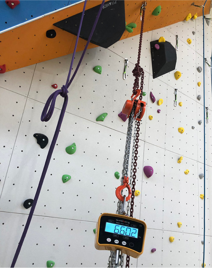
- in addition to the structure’s own load, it is necessary to add the fall load of a climber = break: 20.0 kN / service: 6.6 kN.
- impact resistance of surface elements (panels):
- drop three times a 22 Kg sledgehammer from a distance of 1.50 m in the centre of the 1 m2 surface sample, without observing any rupture or crack.
- resistance of the climbing hold insert:
- pulling on the hold (progressive load up to 12 kN), without observing any rupture or release.
LANDING TESTs
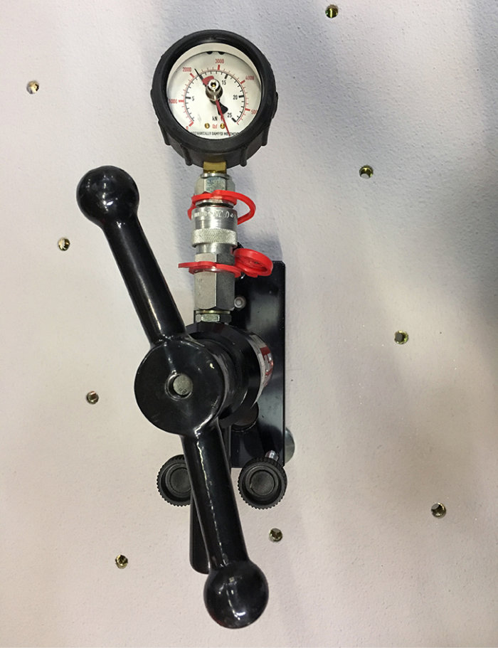
- application of a test load of 6,6 kN (angle 12,5°) for 10 s on the following:
- the first 3 individual belay points of each section
- the highest belay point of each section
- all relay belay points
- drop zone :
- no obstacle or edge that could seriously injure the user in a volume 2 m deep, 3 m wide and 8 m high (above wall/floor) in front of a belay point.
Marking
- manufacturer’s contact information
- contact details of the importer/supplier.
- standard references (EN 12572-1:2017)
- installation date
- date of the next main inspection
Notice
- Repetition of marking information
- location + type of belay points
- maximum number of belay lines
- list of specific requirements for use, maintenance and inspection
CoMPLIANCE
- verification by calculation note
- testing (first install only)
- marking
- user manual and maintenance instructions
CHECKS AND MAINTENANCE
Routine inspection :
- Visual inspection from the ground to identify defects and potential hazards on the façade of the climbing wall before use.
Operational checks: every 1 to 3 months
- verification of the operation, stability and wear of the components in accordance with the manufacturer’s instructions
- logging the inspection in a written report
Main inspection / maintenance:
- in accordance with the manufacturer’s maintenance manual
- verification of the overall safety level of the ACS: structure + surface + safety points
- possible replacement of parts = corrective maintenance + preventive maintenance of critical elements by competent personnel and covered by civil liability insurance
- assessment of the security environment
- recording inspection and maintenance in a written report
EN 12572-2 – approved standard (2017)
Artificial Climbing Structures (ACS) – Part 2: Safety Requirements and Test Methods for Bouldering Walls.
requirements
- maximum height:
- 4.00 m if standing possible at the top.
- 4.50 m without standing possible.
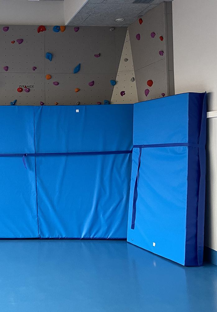
- Cushioning of falls :
- mats with straps
- gravel possible if the height of the bouldering wall does not exceed 3 m or individual mats for walls greater than 3 m
- water / air cushion / net / rubber / cork
- landing surface :
- in front of the wall: between 2.00 m and 2.50 m from the overhang to the foot of bouldering wall.
- on the sides: 1.50 m or 50% of the height depending on the case.
- stability and strength of the structure, calculation method:
- resistance of the components and fixed and variable loads on the bouldering wall: weight of the structure + 0.8 kN per climber + 0.4 kN / m2 or 1.6 kN / m2 if standing possible + other loads (snow, wind etc.)
- Ultimate limit state
- impact resistance of surface elements:
- drop three times a 22 Kg sledgehammer from a distance of 1.50 m in the centre of the surface sample, without observing any rupture or crack.
- resistance of the climbing hold insert:
- pulling on the insert (progressive, up to 12 kN), without observing any rupture or release.
- drop zone :
- there must be no potentially dangerous obstacles
Marking
- manufacturer + importer / supplier.
- standard references
- installation date + date of the next main inspection.
- specific instructions and safety marking..
INSTRUCTIONS MANUAL
- repetition of marking information
- inspection and maintenance requirements
- maximum number of climbers allowed, and additional load allowed per m2
- notices and instructions
- routine checks, operational checks and main inspection
EN 12572-3 – APPROVED STANDARD (2017)
Artificial Climbing Structures (ACS) – Part 3: Safety requirements and test methods for climbing holds.
REQUIREMENTS
- material :
- no hazardous substances
- ergonomic :
- no possibility of sticking
- no sharp edges
- resistance :
- heat/cold/humidity tests
- tightening test
- rupture resistance :
- 2,4 kN for 1 minute
- dimensions
- ratio of the attachment hole to the placement of application of the load < 3:1
- hold size:
- from 0 to 50 mm = XS
- from 51 to 80 mm = S
- from 81 to 130 mm = M
- from 131 to 210 mm = L
- from 211 to 340 mm = XL
- from 341 to 500 mm = XXL
- > 551 mm = “macro”
manufacturer information
- instructions for use, repair, disposal
- maximum tightening torque
- tips for use
Marking
- individual marking (manufacturer/supplier logo) and identification system.
NF S52-400 – approved standard (2005)
Play equipment – Attachment points of sports equipment to its supports – Functional and safety requirements, test methods
requirements
- general requirements:
- no permanent deformation during use
- no displacement of the support or attachment at the end of the tests
- no dangerous protrusion
- specific requirements:
- calculations or tests
- support requirements:
- must be capable of receiving the attachment points and the transmitted forces
- the owner and/or contracting authority of the support is the only one entitled to authorise the installation of the attachment points and the tests
- verification and maintenance recommendations:
- frequent routine visual inspection
- functional checks every 1 to 3 months
- main annual inspection
- inspection procedure
- modifications and safety of users
NF S72-701 – approved standard (2008)
Procedures for the inspection and monitoring of PPE and similar equipment
- methods of inspection of materials:
- lifespan and history
- causes of withdrawal after a routine check
- causes of disposal after further inspection
- list of controls, by type of PPE
- frequency of inspections:
- routine check
- before and after each use
- complete inspection :
- at least every twelve months
- after an exceptional event
- after a removal following a routine check
- routine check
- maintenance and storage
- register
- life record:
- it must follow each material or batch and indicate the exceptional events and inspections undergone
- identification of materials
- life record:
- competency of inspectors:
- know the current standard, know how to check, use and operate the PPE
- hold a State Certificate in climbing, mountaineering, caving
- be certified or qualified specifically for PPE
- other
- informations to be provided to the user
NF P90-312 – approved standard (2007)
Landing equipment for Artificial Climbing Structures (ACS) – Safety requirements and test methods.
The climbing walls concerned are climbing walls that comply with the NF EN12572 and following standards.
security requirements
- landing equipment :
- deceleration, static rigidity, etc
- sizing of the landing area:
- the size of the landing area must be 2,50 m from the overhang to the ground from a line 3,00 m above the ground on the ACS, in all possible directions of a fall
- the thickness should 10 cm maximum from the floor surrounding the mat
- connections between modules
- non-slip features of the base
test methods
- principle, apparatus, procedure
instructions for use
- maintenance conditions
- terms of use
Marking
- “landing equipment for ACS”
- reference to the standard “NF P90-312”
- manufacturer’s name
- year of manufacture